Ceiling Suspended Retractable Batting Cages – 3/4″ Mesh – Call for Quote

Multi-Sport

Description

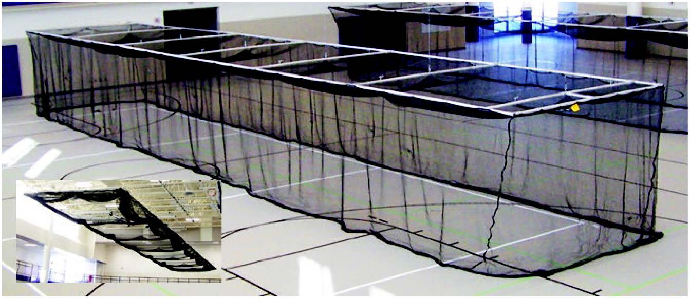
The Ceiling Suspended Retractable Batting Cages  mechanically raise and lower from the ceiling by an electric winch controlled drive shaft.   The cages lower to the floor when in use and raise to the underside of roof structure when not in use for convenient storage.

  • 2” heavy-walled aluminum tubing design
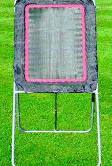
  • Tunnel net included
  • 1’ of netting to lay on the floor when the cage is in the lowered position
  • A cage frame is provided to support and define the cage dimensions
  • Multi-Sport  –  3/4″ mesh (BBC-700M)

Ceiling Suspended Retractable Batting Cage  Dimensions : 70’ L x 12’ W x 11’ H

Sold as 1 Each

  • 14’ wide cages and custom sizes available – call for quote
  • Ceiling mount kit sold separately
  • Also Available for Baseball
  • See “Additional Information” for set up and specifications


Additional information

Weight 675 lbs
Batting Cage Dimensions

BBC-700 – Electric operated baseball batting cage, BBC-700, shall be 11' H x 12' W x 70' L complete with frame, net, fittings, cables and electric winch for lowering to floor when in use and raising to underside of roof structure for storage. Custom sizes are available upon request.

Cage Netting

Baseball Netting 1-3/4" Square #42 Black Nylon (STANDARD)
Multi-Sport Netting 3/4" Square #252 Black Nylon

Cage Perimeters

All perimeters of the cage shall be sewn together bound to a 3/8” polypropylene rope. The cage shall be of sufficient size to allow for approximately 1’ of netting to lay on the floor when the cage is in the lowered position.

Cage Frame

A cage frame is provided to support and define the cage dimensions. The cage frame is constructed of 1.90” OD x .145 Wall Aluminum tube with galvanized malleable iron T and L fittings with case hardened setscrews making a rigid rectangular structure. Cross supports are spaced symmetrically along the length of the cage

Frame Storage

Lowering the frame and placing the side material on the top of the Frame accomplish storage of the cage material. The frame is then raised, allowing for maximum clear height under the cage in the stored position. The BBC-700 and the “V” style hoist is recommended for ceiling heights in excess of 28’.

Hoise Cables

Cage shall be hoisted by individual (7) 1/8” diameter steel aircraft cables (1800# break strength) secured to the drive pipe and encased within formed cable guides. Hoist cable lines shall be placed symmetrically across the length of the cage frame. Hoist lines terminate at the cage frame at 21 locations utilizing a “V” style attachment. This attachment is provided to stabilize the ends of the frame and keep it parallel with the floor. The “V” style attachment provides maximum attachment points to the cage frame. The hoisting is designed so that no one cable is dedicated to the entire load of the cage. Single hoist cable “Clew” system shall not be approved as equal. Suspension from roof support member shall be accomplished with clamp type malleable fittings furnished by the manufacturer.

Drive System

he drive system shall consist of a UL listed, 1HP 100VAC 60Hz Single-phase compensating type instantly reversible winch. Winch shall be capacitor start with build in thermal overload protection. Winch shall be direct drive, self lubricating gearing and require neither belts nor oil baths. Winch shall have unique built-in POSILOK™ over-speed arrest system. Winch shall be Jaypro Model CW-1800. Drive pipe shall consist of 2-3/8" OD galvanized pipe and shall be supported with hanger/rollers. Support assemblies shall be spaced approximately 12" from the cable guides along the length of the drive pipe. The drive pipe shall pass through and be secured to the winch drum and rest and rotate on the support assembly rollers.

Winch Specifications

Winch shall be supplied with a 3 position key switch and polished wall plate which shall be located in clear view of the cage to ensure unobstructed view during operation. Switch shall fit into a 3" x 2-1/4" x 2-1/2" (H x W x D) device box supplied by others. Integral upper and lower limit switches will control the upper and lower travel of the cage. Optional control of the cage can be accomplished with the following systems:

ETEC Easy Touch Equipment Controller (Refer to ETEC Specification Sheet)
MEC PAD Master Equipment Controller (Refer to MEC-99 Specification Sheet)
TMX-DRX Wireless Radio Remote (Refer to TMX-DRX Specification Sheet)

Wiring

Wiring of all electrical components shall be in accordance with national and local electrical codes, as well as specific wiring instructions provided.

Reviews

There are no reviews yet.

Only logged in customers who have purchased this product may leave a review.